The Rail System
Stage II
The Rail System
The sliding components of the rail system should be made of vassa for extended durability and reduced friction. For the trays to run easily and reliably the rails must be level and equal-spaced along their whole length. Tolerances for the rails are within 1cm. on each side. Construction using hand-milled timber will inevitably require clamping to ensure correct placement while nailing.
 Rail Supports: Before the flooring goes down use pre-built trays to mock up the internal layout of the rail-transport system, cramping the rails to the joists.
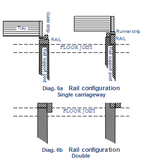
Different layouts and rail configurations are possible:
a decision is needed before proceeding further.
Two examples of single-rails are illustrated in Diagram 6a. Note their relationship to the floor joists. In Diagram 6b the same two rails have been modified into double-rails. Neither type of rail can be expected to give better overall performance.
Rather, optimum performance of the completed system is more dependent on accurate layout and careful construction during the set-up stages.
After deciding upon a rail configuration use a string-line, level and pegs to define positions for the rail-support posts. Cut to length (post height) and notch out the posts only after they have been firmly buried in, adjusting the cuts to allow for variations in thickness and width of individual rail timbers.
Cramp the rails into place and check again before nailing them down.
The middle rails
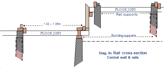
The middle rails for each level are double-rails, supporting two trays – one on each side. The examples from Diagrams 6a & 6b are combined in Diagram 6c, which also illustrates a possible configuration for the rail which sits over the central wall.

Note that the layout of the rail-support posts do not necessarily line up with building support-posts.