Framing up the Structure
3. The construction sequence:
Builders can vary the actual sizes and dimensions from those given. That will work as long as the logic of the construction method is understood so that each piece gets sized and fitted accordingly.
The method outlined here starts with the construction of a hillside model. Specifics for the centrally-vented model follow in a later section.
Stage I

Lower chamber joists
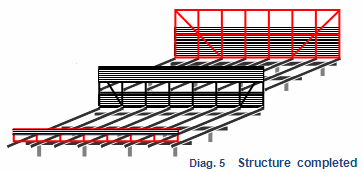
In Diagram 4 all the (4) bearers have been set on their pre-notched posts with their ends cut to length (4.2-4.4m), square to the central wall. The joists for the lower level have also been fasten into place, extending (0.1-.2m.) over the central wall. The timber cap (vassa) on the central wall is also shown. Later this must be extended along the concrete wall to carry the rails.
- The mid-wall frame is now being fitted. It must be positioned uphill of the concrete wall, allowing enough width inside to fit the rail which sits on the wall, (see Diagram 1).
- A timber is then nailed across the mid-wall at a level to support the upper-level joists.
- The lower section of the mid-wall is then walled over from the outside, up to that level.
 Upper chamber joists
- Set the upper-level joists against the mid-wall frame and nail into place, checking for level all the time.
- Put the two end-wall frames in place and check the roof line before affixing.
- Fill in the wall baffles on all (3) frames as shown here, covering 1/3 to ½ of each wall’s surface area.